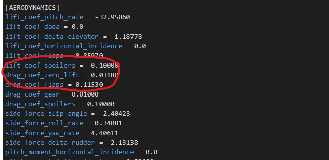
Icon A5: [AERODYNAMICS] section:
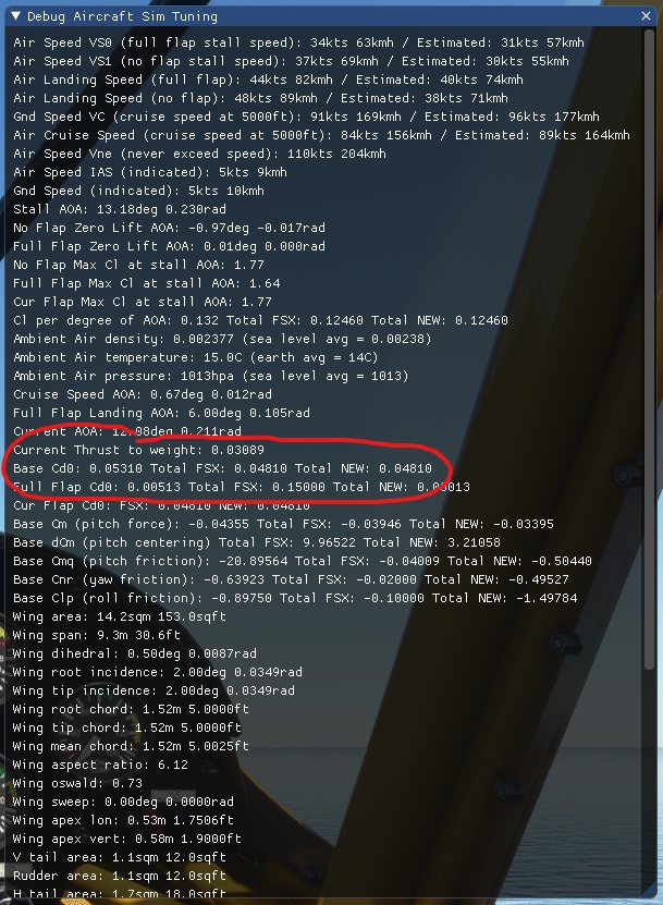
 induced_drag_scalar = 1
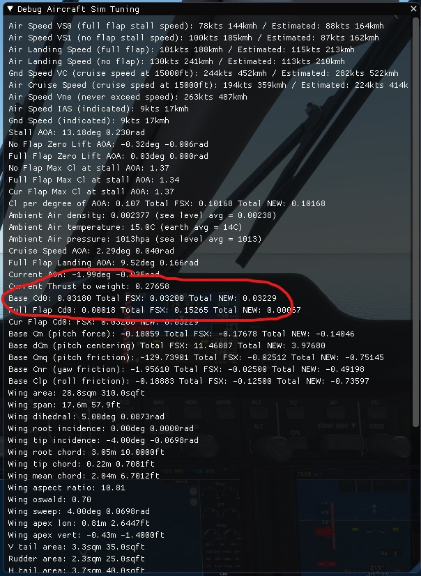
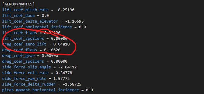
(default value):
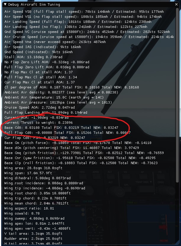
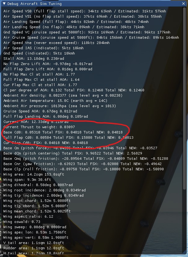
induced_drag_scalar = 0 (modified value):
Again, interesting results for
this one.
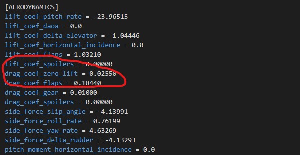
Icon A5: [AERODYNAMICS] section:
induced_drag_scalar = 1
(default value):
King Air 350: [AERODYNAMICS] section:
 induced_drag_scalar = 1
(default value):
Pitts: [AERODYNAMICS] section: 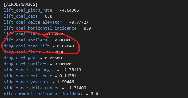
induced_drag_scalar = 1 (default value):
Savage Cub: [AERODYNAMICS] section:
 induced_drag_scalar = 1.5
(default value):
TBM 930: [AERODYNAMICS] section:
 induced_drag_scalar = 1
(default value):
VL3: [AERODYNAMICS] section: 
induced_drag_scalar = 1 (default value):
XCub: [AERODYNAMICS] section: 
induced_drag_scalar = 1.25 (default value):
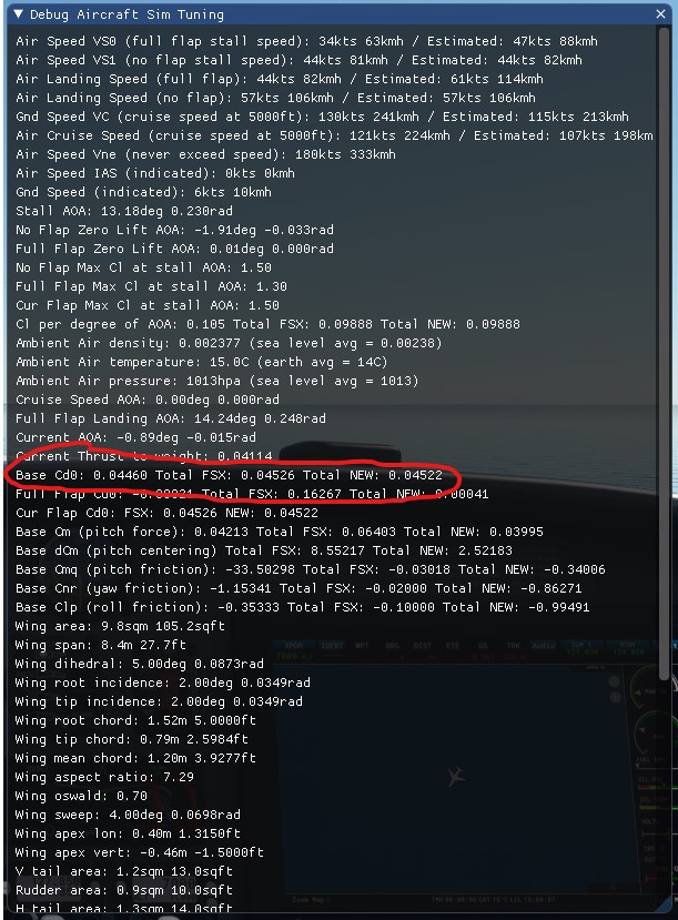
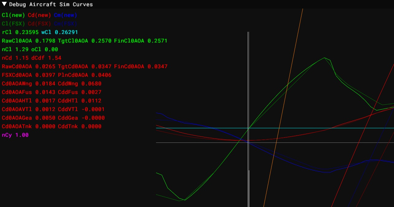
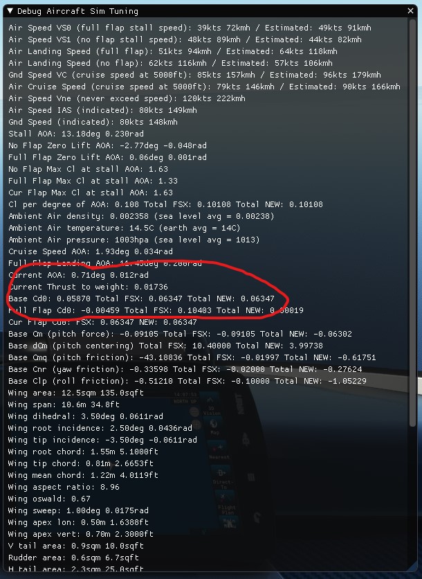
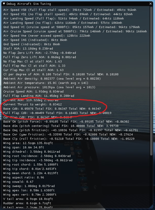
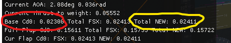
Hello Bouforge, There seems to be a misunderstanding here and I think it comes
from our current debug panel not being very clear. The values displayed after
“FSX” and “NEW” are not Cd0 but Cd with 0 AoA (hence my picture with the
modified naming). Therefore it takes induced drag into account. Regards,
Sylvain
Hello Alec, I understand, we really need to better document that part. We are
actually working on video tutorials about this and expect the doc to be
completed as well. There’s no explicit normalization failure “warning”. It’s
more of a habit of checking that FSX and NEW figures are relatively close or
something is going wrong. I’m sure those video tutorials will answer most of
your questions on this. If you have any suggestions on how to improve the
usability and readability of the AircraftEditor, feel free to create ideas
about this. Regards, Sylvain
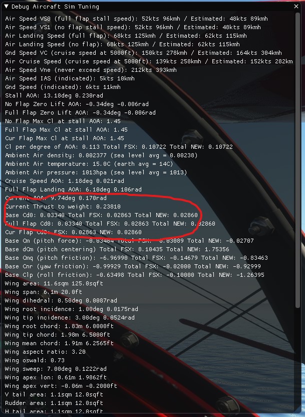
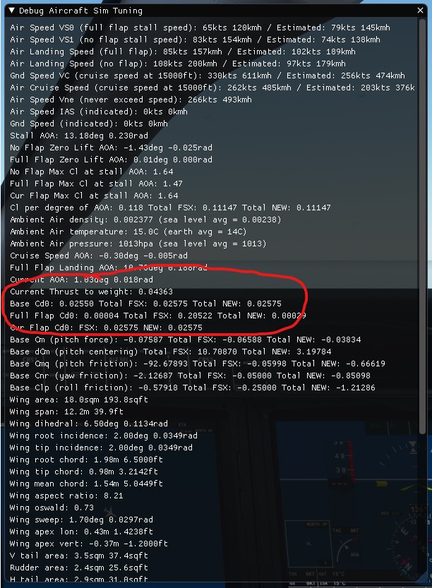
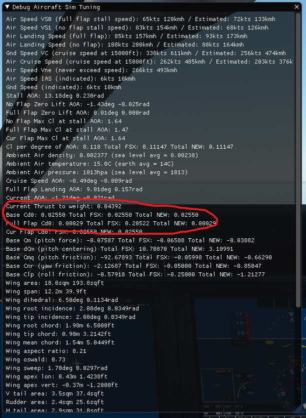
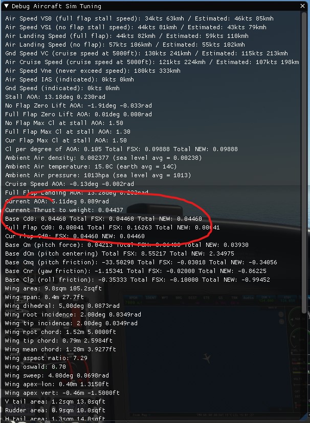
After looking at the results, here are my conclusions for this plane: - for
the default case (induced_drag_scalar = 1.8):
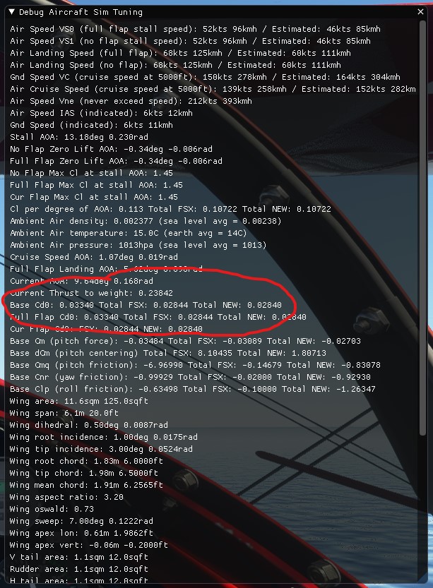
- for the modified case (induced_drag_scalar = 0):
Merci Sylvain for the answer. It makes a lot more sense and I wish the debug
tool was clearer. I have noticed something else that I quite can’t understand
and it is the fact that for fixed landing gear aircraft, the
induced_drag_scalar appears to have an effect on Cd by excluding the
drag_coef_gear in the Total NEW value. I will tag you in the comment about the
DA40NG results, it will be easier for you to find them that way. Cheers,
Romain EDIT: tried tagging you in the results but it doesn’t seem to work…
@FlyingRaccoon, here is my interpretation of the results. See how the
induced_drag_scalar influences the Total NEW value by excluding the
drag_coef_gear value.
This is a convention we use. To prevent having to set the gear drag in
different places, depending on if this is a fixed or retractable gear, it is
always defined in the drag_coef_gear. It means the Cd0 we set for an aircraft
with fixed gear doesn’t actually take the gear into account. The influence of
the gear in the Cd will come from the drag_coef_gear. Regards, Sylvain
That is excelent Sylvain! Keep documenting and the Addons will only improve
with time. I will be more aware of the FSX and NEW values. Is there any
estimate on when these new improved nomenclatures will arrive at the SDK? I
will sure create some posts with IDEAS in the future! I can already think of
some! Regards
Sorry for not replying before, but the flying schedule is looking busy again.
Thanks for the clarification on the gear drag being excluded from the Cd0, I
think it is quite unique as it’s my understanding that it is normally included
as a convention in the Cd0 for fixed gear aircraft. Why is it that when I set
induced_drag_coef = 0 the gear drag is not being applied anymore? I’ll copy my
comments on the DA40NG down below, but I think they apply to all the fixed
gear aircraft. Thanks again!
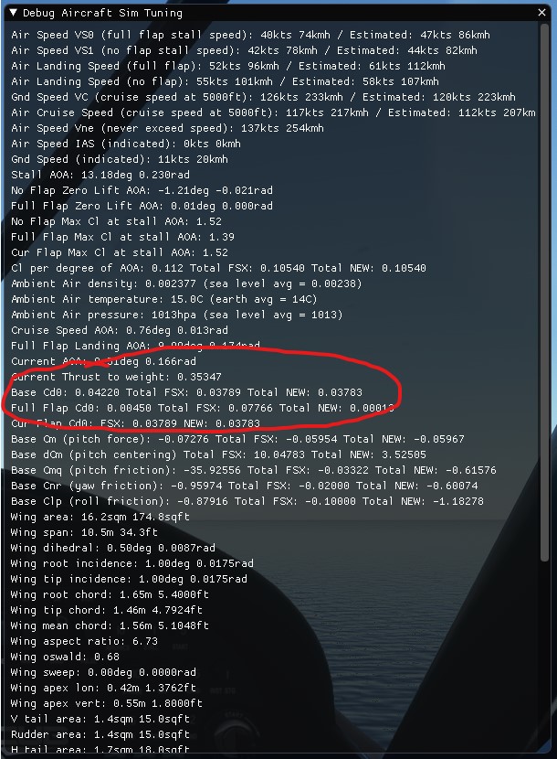
Under DA40NG screenshots comment: After looking at the results, here are my
conclusions for this plane: - for the default case (induced_drag_scalar =
1.8):
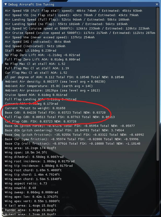
- for the modified case (induced_drag_scalar = 0):
See that in the modified case, the gear drag is not included in the Total New
value when it is in the default case. I wonder why, since only the induced
drag should be removed.
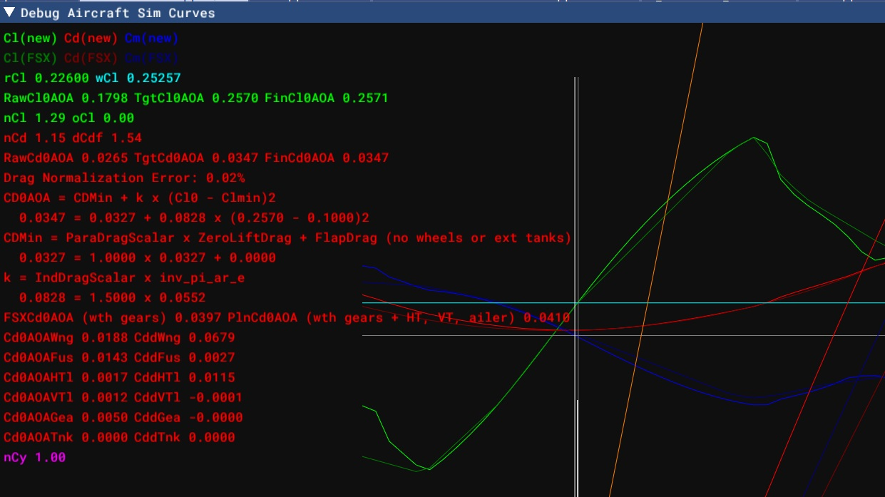
Hello, @FlyingRaccoon, sorry to come back to this, but I think this is a bug
in the end and that this is not only a matter of a wrong label in the debug
windows. When opening the Sim debug window, the window showing all the curves
is showing the Cd0 and the Cd0 shown there is including the induced drag at
AOA=0°, which it should not. I calculate the exact same value by doing Cd =
Cd0(from the file) + k (Cl(AOA=0°) - Cl0)² in an Excel spreadsheet. Here is a
screenshot showing this: 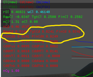
Hello @boufogre @Alec246 It’s a bit late but I finally had some time with our
FM expert to review these issues. Here’s a bit more content to help you
understand our process: _
@Nocturne FYI