Understand tables and formatting?

I’m trying to understand tables, and how they work.

Please have understanding.

For example, there is a table called the following: drag_coef_zero_lift_mach_tab

The MSFS SDK describes it like this:

Adds drag based on the mach level. In the modern flight model, the drag coefficient at higher mach levels is automatically impacted by a progressive detaching of the laminar airflow over the surfaces. However this table allows to add more drag at specific mach levels to simulate a mach wall or specific effects of drag due to turbulence at specific drag levels. Drag walls are not natively simulated yet and will need to be defined with this table. The table has a maximum of 17 entries and the format:

mach:drag_coef,
mach:drag_coef,
mach:drag_coef,
etc…

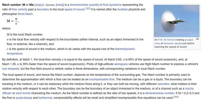
Also why do MSFS call it mach level, and not mach number?

The first question is about formatting. How you can or must write the table.

For example. it seems that most flight models have the table formatted in a long line, which makes it very difficult to read. Is there a reason they do it?

Take for example, FBW A320 drag_coef_zero_lift_mach_tab

They have written it like this:
drag_coef_zero_lift_mach_tab = 0:0, 0.5:0, 0.55:0, 0.6:0.0002, 0.65:0.0003, 0.7:0.0004, 0.75:0.0008, 0.8:0.0015, 0.85:0.010, 0.9:0.15, 0.95 :0.333, 1:0.5

The question is then, could it just as well have been written like this:

drag_coef_zero_lift_mach_tab =
0:0,
0.5:0,
0.55:0,
0.6:0.0002,
0.65:0.0003,
0.7:0.0004,
0.75:0.0008,
0.8:0.0015,
0.85:0.010,
0.9:0.15,
0.95:0.333,
1:0.5

Or is there some reason that most aircraft cfg files are formatting the tables in a long unreadable line?

The next question is about the actual numbers:

If I understand correctly the first number is mach speed?
which in FBW’s case becomes mach 0, then mach 0.5, then mach 0.6 and so on.

If I understand this correctly, they have entered these values in the table to increase drag with speed, above drag_coef_zero_lift?

If I then take their value of drag_coef_zero_lift = 0.01873
Can you then say that at mach 0.6, drag will increase by 0.0002?
Which in that case would be 0.01873+0.0002=0.01893

Do I understand this table correctly that at mach speed 0.6 the drag without flaps and wheels"cleean config" will be 0.01893?

Could they have written table like this?

drag_coef_zero_lift_mach_tab =
0:0,
0.5:0,
0.55:0,
0.6:0.0002,
0.65:0.0003,
0.7:0.0004,
0.75:0.0008,
0.8:0.0015,
0.85:0.010,
0.9:0.15,
0.95:0.333,
1:0.5

So if I understand correctly, the most important thing in understanding the tables is what they refer to, or where they remove or add properties.

Is it also correct that most tables have become unusable in “modern flight model”?
Eg: lift_coef_horizontal_incidence_mach_table which if I understand correctly changes the “lift” of lift_coef_horizontal_incidence?

[SDK]
Defines how much lift will be added to the overall lift formula based on the current yaw angle of the aircraft.

This is a legacy FSX parameter not used in the modern flight model. In the modern flight model this effect is natively obtained through aerodynamic simulation of the surfaces defined in the [AIRPLANE_GEOMETRY] section.

In the FBW flight model they have included this parameter, but set it as 0? They have also set the corresponding table as 0.
(lift_coef_horizontal_incidence_mach_table = 0:0)
Do you have to include parameters that are not used by e.g. modern flight models?
Do you have to write 0:0 or is it enough to write only =

Then I come to the next question. If I’m not wrong, e.g. PMDG uses modern flight model. Then the question is why have they included a parameter that is not used by modern flight models.

They have, for example:
lift_coef_horizontal_incidence=1.891602

lift_coef_horizontal_incidence_mach_table=0.000000:0.000000, 0.200000:0.003908, 0.400000:0.009770, 0.600000:0.040059, 0.800000:0.160234, 1.000000:0.08 2071, 1.200000:0.048852, 1.400000:0.048852, 1.600000:0.047875, 1.800000:0.048852, 2.000000:0.047875, 2.200000:0.048852, 2.400000:0.048852, 2.600000:0.048852, 2.800000:0.048852, 3.000000:0.047875, 3.200000:0.048852

For example, they have defined the aircraft as:
modern_fm_only=1

This should mean that none of these lines have any effect on how the aircraft behaves?

I understand that no one but them can answer why they have done so.
But is there something I’m missing. Should they have done like FBW and just put 0?

I think they might use these in case they become relevant. Or to remember aircraft behavior.

But when you construct an aircraft model, what is the correct way to do it? FBW or PMDG style?

Many questions, very grateful for answers.
The .cfg file format that MSFS uses is

<config parameter name> = <value>

WITHOUT line breaks, regardless of the format of the <value>

Parameters described as “legacy” are supposedly not needed in the flight model if you set the parameter that says “modern flight model only”. However, if you delete all these parameters MSFS will crash-to-desktop so in practice we all (including Asobo) leave those parameters in the flight_model.cfg file. By far the best approach is to collect all those “legacy” parameters and put them together in a “these parameters are obsolete” section in your file, and Asobo should do the same with the SDK docs instead of scattering them through the file mixed in with the “modern” parameters. Even Asobo is unsure which ‘legacy’ parameters are still needed so we all just leave them in the flightmodel.cfg with ok-looking numbers from some previous aircraft.

“drag_coef_zero_lift_mach_tab” works the way you suggest, ADDING a number to the drag coefficient interpolated from the pairs of numbers in the . I don’t know why ‘mach level’ instead of ‘mach number’, but you can look up the number in the SDK ‘debug speed’ window. Incidentally you can see it working in the SDK Debug “drag” window. The mach level of the FIRST entry must be zero or MSFS crashes. This cfg parameter is EXTREMELY useful, it allows you to adjust the drag value for ANY speed of the plane and hence tailor the glide ratio at any speed - it has nothing inherently to do with sound barriers or any other physical process. We use it for gliders to fine-tune the crucial lift/drag ratio at all speeds ( = glide ratio) and without that parameter we’d really struggle to get an accurate glide polar curve.

Thanks so much. Very useful information, I’m slowly but surely starting to learn more and more about how it works.

Could you please share these tables, what confuses me is that mach speed is usually used above a certain speed, and gliders usually fly at a much lower speed. 100-250 km/h. It would be interesting if I could learn how you/you use these in a much slower moving aircraft.

Can you use minus values in most tables, for example -0.0002.

Or is it better to lower the general value: drag_coef_zero_lift = and change drag with drag_coef_zero_lift_mach_tab “plus” values. Which adds “drag”.

For example, if I now have a value from a Boeing 737-800 where according to the document I have, the value “CdO clean” is 0.021 and according to someone here, Cd0 is the same as drag_coef_zero_lift.

Then I think I could use the value in the document which is 0.021 and then use drag_coef_zero_lift_mach_tab and write partial minus values to match the other drag data I have. Example at 240 knots= 0.3628278Mach, I know the plane should decent with 1300-1350 feet. And with 0.021 the plane descends with 1500 or something. I now understand that I first should set the drag_coef_zero_lift_mach_tab to 0, collect data and then mach my numbers with the corect drag tabel? Or am I thinking wrong?

So should I start with as correct geometry data as possible, make all tables 0 then add all values I could get hold of, and then start applying Table to match the real numbers?

Are there any tables to be careful with or that are difficult to understand? Anyone you want to warn against messing with too much?

Once again, many thanks for the reply.

I can’t answer the more specific questions about programming a 737 but I’d suggest for a subsonic aircraft you should start with the mach drag adjustments at zero and see what performance the MSFS flight model gives you. Note that parameter is mechanically a way of fine-tuning drag at any speed, so it’s equally useful for gliders at slow speed as it is for jets at high speed. Also there is no such thing as a general “these parameters are good, these are problematic” - ultimately you have to start work on a flight model and learn how the parameters in a complex system interact.

For gliders we have the manufacturer published ‘polar’ (i.e. sink rate at different speeds) as the required truth, not some specification of CD0 or other parameter values. So we’ll set drag coefficients and llift/AoA numbers to try and match each glider’s polar curve, repeatedly measuring the actual glide ratio in the sim (=lift/drag) to see if we’re approaching the real aircraft. This is a laborious process but necessary to get the glider performance right.The MSFS flight model enables you to match the glide ratio at some speeds but typically the glide ratio at other speeds will then be wrong (glider performance is of course extreme). Typically the glide ratio (=lift/drag) if set correctly for a cruising speed will cause too high a glide ratio at slower speeds in the MSFS flight model. Powered plane developers never worry about the RATIO of lift to drag, if that was the case then they would have noticed in FS2002/2004/FSX/MSFS the lift/drag RATIO (=glide ratio) always increases as you slow down, until stall effects kick in. Very recently new flaps and stall parameters give more control over the slow end of the polar.

1 Like